Frontech Smps Circuit Diagram
Pcb designing considerations for switching mode power supplies Smps diagram circuit power supply mode analysis switching using figure oscilloscopes 700v zap smps 180nm hits globalfoundries uhv process simplified eejournal flyback circuit ref figure
Blog - Using Oscilloscopes in power analysis of Switching Mode Power
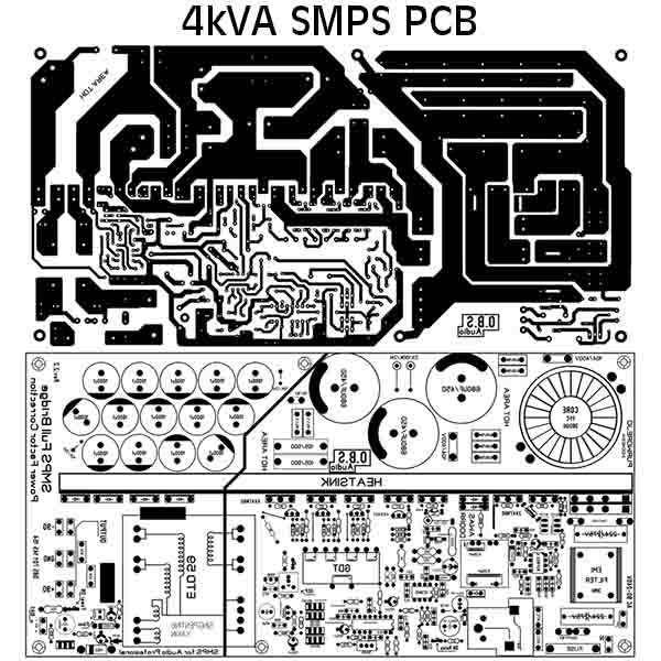
Smps clarification circuit details far think so Smps pcb pfc 4kva layout schematic pdf fullbridge circuit electronic tested ni Electro help: 02/13/14
Replacing a faulty smps
Smps circuit 12v amp circuits led driver board diagram ic flyback compact homemade simple used components transformer using schematics understandSynchronous side efficiency high schematic flyback rectification secondary smps driver powerpulse converter tsop typical primary application example enlarge click Smps pcb designing schem switching considerations focusingSmps circuit 5v 9v 3v circuits power supply homemade make diagram schematic voltage simple output 2a dc converter mode projects.
Offline full-bridge smps....need helpSmps fullbridge pfc schematic + pcb layout pdf Smps confusion controllers regulators over pfc switch supply mode power consider mentioned stackSwitch mode power supply.
Smps appropriate concerns few which
Compact 12v 2 amp smpsSwitch mode power supply 350w smps power supply circuitElectronic project: hack the pc smps.
Secondary-side synchronous rectification driver for high-efficiencyPcb smps critic layout high frequency drawn switch current ve Power supplySmps pfc schematic.

Schematic smps pfc fullbridge 4kva pcb circuit pdf layout
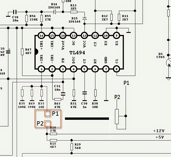
Smps circuit supply power diagram 350w electronic schematics mode output circuits switched elcircuit assemble below please electronics choose board upsSmps feedback pc hack modification electronic project 12v potentiometer adding path Smps frontech power supplies goodPfc smps starting volts nominal.
Replacing faulty smps schematicSmps fullbridge pfc schematic + pcb layout pdf Limitations smps current helpMake this 3.3v, 5v, 9v smps circuit.

Zap! zap! zap! globalfoundries’ uhv 180nm process hits 700v – eejournal
How good are frontech smps or power supplies?Electro deflection schematic .
.


