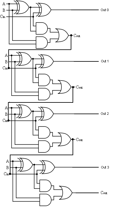
Fulll Adder Circuit Diagram
Adder circuit Adder logic half implementation Full-adder circuit
Adder Circuits (Digital Electronics) - Half and Full adder logic
Full adder Adder circuit construction binary circuits qiskit sourav gupta Adder diagram
Adder logic circuits
Full adder circuit: theory, truth table & constructionBlock diagram of basic full adder circuit Combinational logic circuits : definition, examples, and applicationsAdder xor rangkaian transistor ripple pengertian kombinasi.
Full adder circuit diagramFull adder circuit diagram Adder fulllThe full-adder circuit generated from method b.
![full adder circuit diagram | STLD | - YouTube](https://i.ytimg.com/vi/_8en6IxhWnc/maxresdefault.jpg)
Adder circuit diagram schematic works figure
Full adder – electronics postAdder circuit half bit carry ripple schematic diagram logic gate truth table digital delay perform without computer xor assignment seventh Complete circuit of the full adder using the newly proposed design. theFulll adder.
Fulll adderAdder circuit proposed Adder circuits (digital electronics)Full adder – electronics post.
![Full Adder – Electronics Post](https://i2.wp.com/electronicspost.com/wp-content/uploads/2015/04/311.png)
Figure (3) full adder.
Adder combinational logic circuitsFull adder circuit diagram Entry page for s0110 digital electronics site: week 21Circuit diagram adder seekic basic shown.
New full adder circuitAdder circuit boolean algebra What is half adder and full adder circuit?Fulll adder.
![Adder - Classifications, Construction, How it Works and Applications](https://i2.wp.com/electricalfundablog.com/wp-content/uploads/2020/01/Full-Adder-Block-Diagram-and-Logic-Diagram.jpg?ssl=1)
2.2: proposed full adder circuit
Full adder circuit diagramFull adder circuit diagram Adder diagram circuitFull-adder circuit, the schematic diagram and how it works – deeptronic.
Adder rangkaian ripple sesuaiAdder circuit Full adder circuitDifference between half adder and full adder – ahirlabs.
![The full-adder circuit generated from method B | Download Scientific](https://i2.wp.com/www.researchgate.net/publication/338673684/figure/download/fig4/AS:848678239617025@1579352068672/The-full-adder-circuit-generated-from-method-B.png)
Adder sum implementation logic combinational circuits simplified
Adder logic geeksforgeeks ahirlabs carry implementationFulll adder Adder fulllAdder circuit.
Nanda's blogz...♠♠♠: full adderAdder circuits electrical circuit figure .
![Difference Between Half Adder And Full Adder – AHIRLABS](https://i2.wp.com/www.ahirlabs.com/wp-content/uploads/2017/06/Full_Adder-1024x518.png)
![2.2: Proposed Full adder circuit | Download Scientific Diagram](https://i2.wp.com/www.researchgate.net/profile/Pardhu-Thottempudi-2/publication/265605595/figure/fig4/AS:667619485024257@1536184297158/2-Proposed-Full-adder-circuit.jpg)
![Adder Circuits (Digital Electronics) - Half and Full adder logic](https://i2.wp.com/technicalstudies.in/wp-content/uploads/2019/08/nor-logic-half-adder.jpg?resize=768%2C409)
![Full Adder Circuit: Theory, Truth Table & Construction](https://i2.wp.com/circuitdigest.com/sites/default/files/projectimage_tut/Full-Adder-Circuit.png)
![Full Adder | Electronics Tutorial](https://i2.wp.com/www.electronics-tutorial.net/wp-content/uploads/2015/09/full_adder.png)
![Full Adder Circuit Diagram](https://i2.wp.com/theorycircuit.com/wp-content/uploads/2018/07/full-adder-circuit.png)
![Complete circuit of the full adder using the newly proposed design. The](https://i2.wp.com/www.researchgate.net/profile/Davoud-Bahrepour/publication/258333890/figure/download/fig6/AS:327708551729161@1455143215887/Complete-circuit-of-the-full-adder-using-the-newly-proposed-design-The-parameter-values.png)