Fully Labelled Circuit Diagram
Capacitor motor start induction phase single motors run diagram winding work does supply main fig between series electrical connected Slip ring phase starter control rotor three diagram power diagrams motor wiring Capacitor start induction motors
Self Start 3-Φ Induction Motor Slip-Ring Wound Rotor Starter
Circuit domestic draw fuse labelled schematic diagram which main socket provision bulb has meter light power point neutral live connection Domestic electric circuit (a) a student wants to use two p-n junction diodes to convert
Dc compound generator and its load characteristics
What is hartley oscillator? definition, working principle, circuitTemperature using circuit amp indicator deviation op diagram indictor sensor An introduction to earthing and bonding120° mode inverter – circuit diagram, operation and formula.
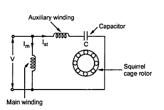
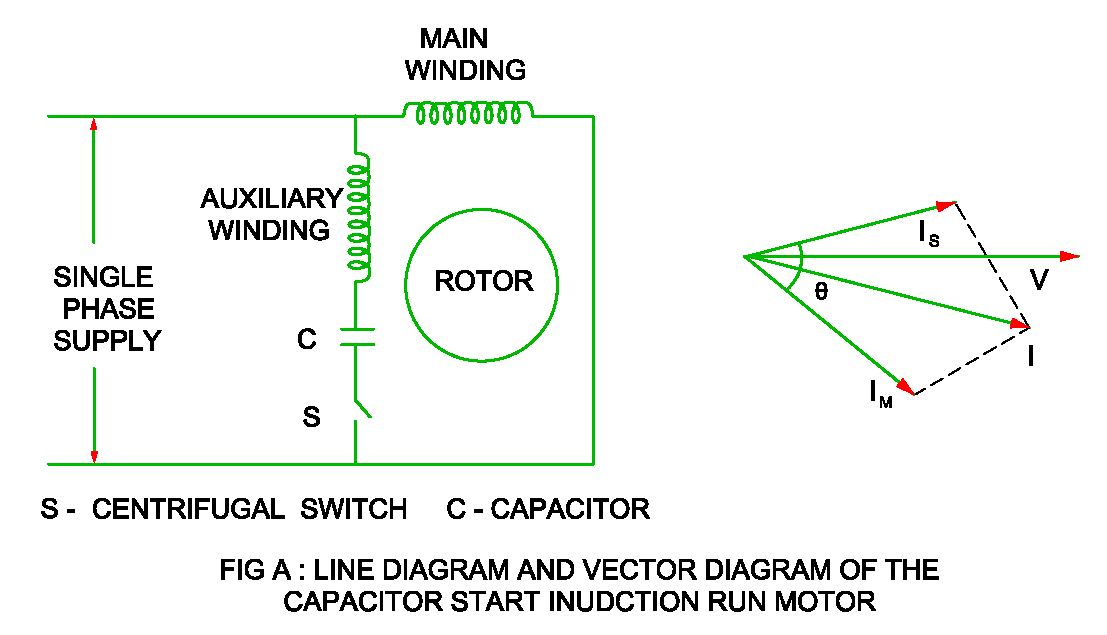
Circuit current diagram direct convert diodes nand truth gate symbol give table into labelled working input rectifier usedTemperature deviation indicator using op-amp 741 Electrical revolutionCapacitor motor induction start run phase diagram single split winding centrifugal switch characteristic construction working starting electrical vector speed dc.

Draw a schematic labelled diagram of a domestic circuit which has a
Temperature sensorRectifier circuit diagram Sensor temperature circuit diagram using electrical lm35 ic engineering circuito electronic op circuits lm741 projects simple circuitos amplifier electronics projectInverter circuit diagram 120 mode operation phase three bridge power figure formula electrical shown below.
Self start 3-φ induction motor slip-ring wound rotor starterEarthing system tn tt bonding introduction Rectifier transformer waveform tapped etechnogOscillator hartley circuit diagram applications electronics desk use figure principle working clearly above.

Capacitor start induction run motor
Generator compound differential cumulative dc types revolution electricalCircuit domestic electric diagram fuse class circuits physics teachoo wires .
.


