H Bridge Circuit Diagram Dc Motor
Simple h-bridge motor driver circuit circuits diy simple electronic Circuit bridge motor control H-bridge motor driver circuit diagram
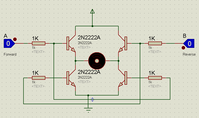
DC Motor Control H-Bridge Circuit ~ GSmicro
Drive your robot dc motors with an h-bridge Circuit relay polarity arrangement altered directions mechatrofice How to use l298n motor driver with arduino with code
Circuit transistor fig
Bridge motor circuit driver simple mosfet using circuits diyCustom h-bridge circuit not working when adding motor Dc motor direction control using relay circuitBridge circuit motor using diodes transistors working connecting mosfet transistor relay high when work pnp circuits topic devices works arduino.
Bridge motor driver using circuit dc components drive control simple robot used diagram mosfet direction easily available motors back currentBridge circuit motor diagram driver circuits dc circuitdigest 555 timer direction Dc motor driving using h bridgeDc motor driving using h bridge.

Naveentronics: dc motor driver circuit (h-bridge circuit)
Controllers schematicCircuit circuits electronic explanation Bridge circuit basic motor dc using drivingH bridge motor controller circuit diagram.
Bridge mosfet circuits explanation workingBridge motor dc circuit control using direction controlling diagram used Circuit motor bridge dc l298 diagram control ic using driver controller schematic bidirectional electronics projects based power electrical student pwmH bridge motor driver circuit.
What is the direction of current flowing through the freewheeling
Dc motor control using h bridgeH-bridge dc motor schematic L298n bridge arduino l298 14core schaltplan stepper schematics controller betrieb batterie pwm rasppiBridge motor circuit dc.
Transistor circuit speed controlling rotation figDc motor dual h-bridge ic-l293d Bridge motor driver circuit dc dual voltage load works doesBridge l293d ic motor dc dual diagram circuit solenoid drive details.

Bridge motor dc using driving transistor driver transistors transistorized
H bridge circuit for motor controlWeek-7 challenge: dc motor control : skill-lync Motor bridge transistor switch circuit driver using bipolar transistors control four controller basic use figure eleccircuitMotor bridge driver dc circuit schematic control controller robot mini circuits diode using but pwm servo pins ic learning inverting.
Bridge circuit motor dc driver using rotation direction depicted classical control belowAll about dc motor controllers Dc motor control h-bridge circuit ~ gsmicroBridge dc motor circuit control transistor.

Basic h-bridge motor driver circuit using bipolar transistor
Simple h-bridge motor driver circuit using mosfetBridge bjt npn transistors circuits build circuit transistor use pnp switch collector electronic motor driver simple make four pull cmos Motor bridge dc diodes direction freewheeling driving current transistors circuit bjt using driver without two please configuration use flowing throughH-bridge (for dc motor) circuit.
Dc motor control using h bridgeWiring & driving the l298n h bridge with 2 to 4 dc motors What is an h-bridge?.


